Connecting up an Enphase M215/M250 solar inverter
for testing without the necessary plug
(Last update 2026-07-31)
The planned setup
The Actual setup
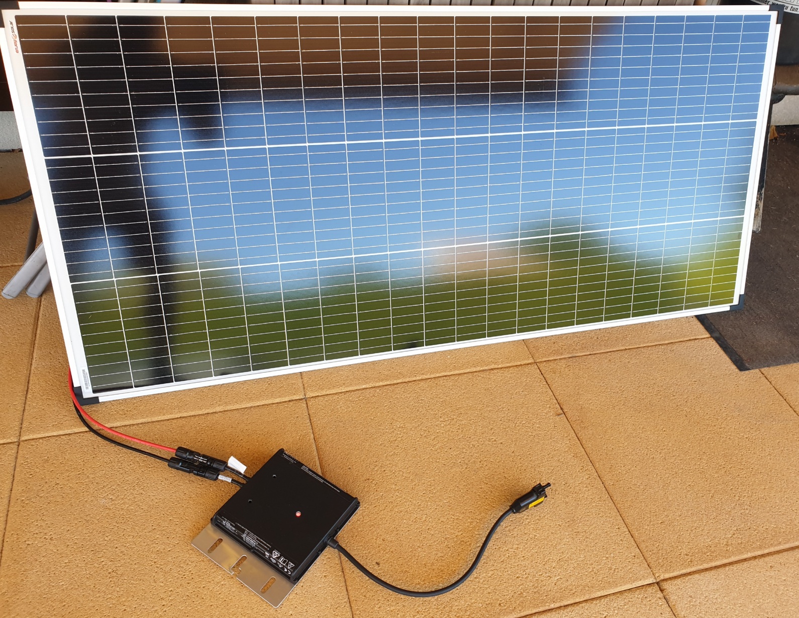
It comes with this special proprietary plug
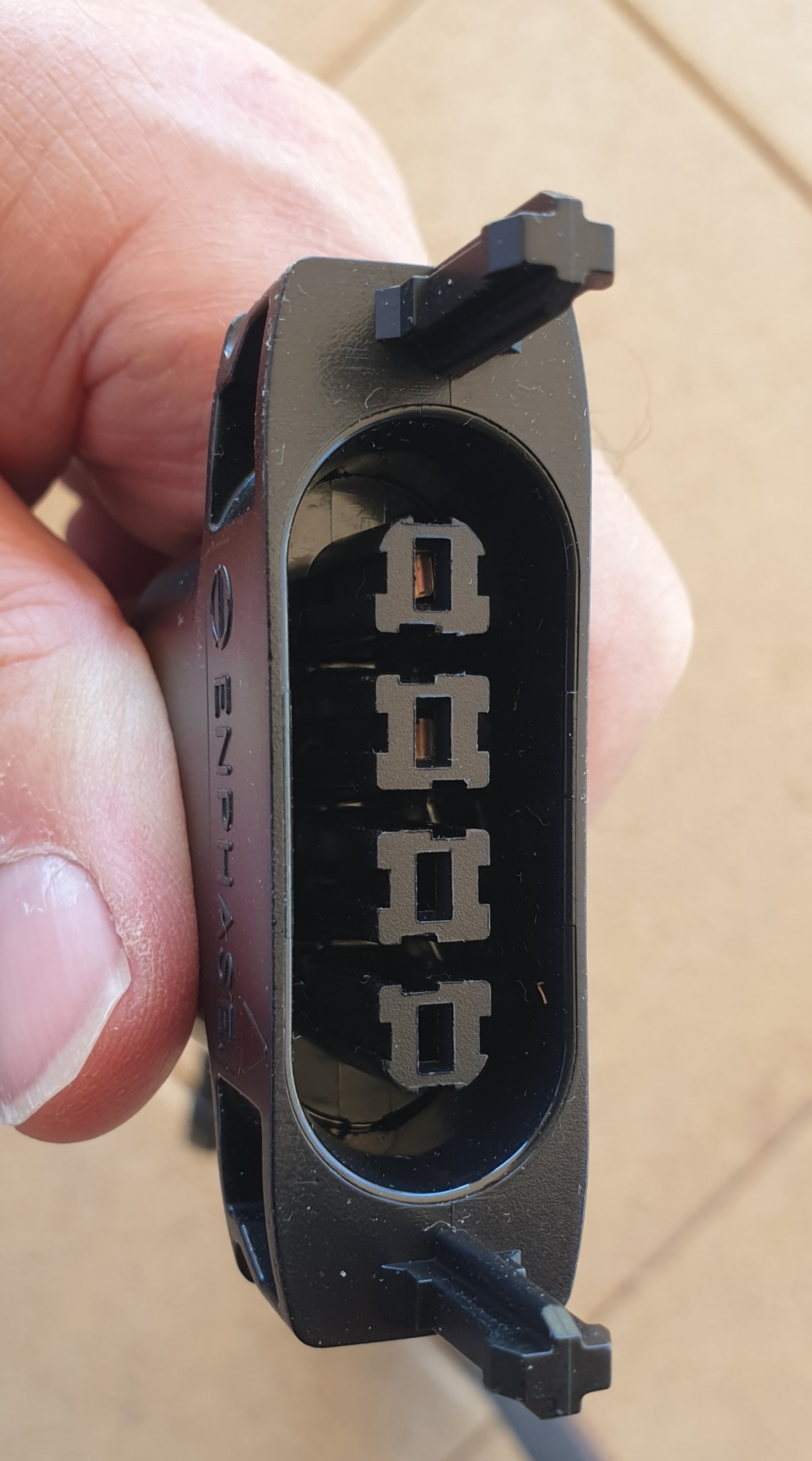
normally installed on the roof
The socket alone is not commercially available as it is proprietary.
even trunk cabling is hard to find
So let's make a socket instead,
how hard can it be, here's how it was done
With Claude's assistance we made a script to implement my design
which was then created in Blender
and subsequently printed on the Bambu P1S printer
with the following results
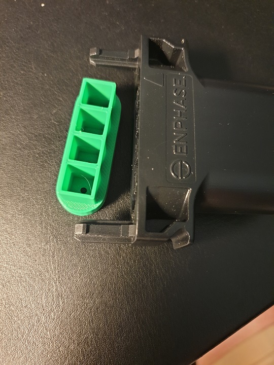
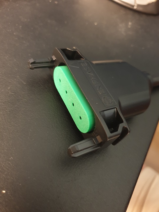
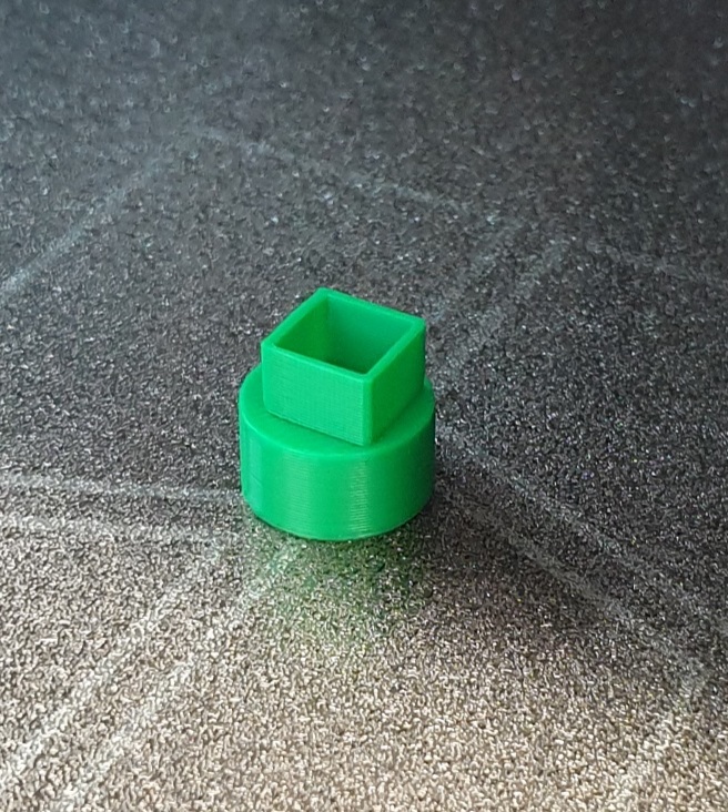 First test to check shell and pillar size and fit |
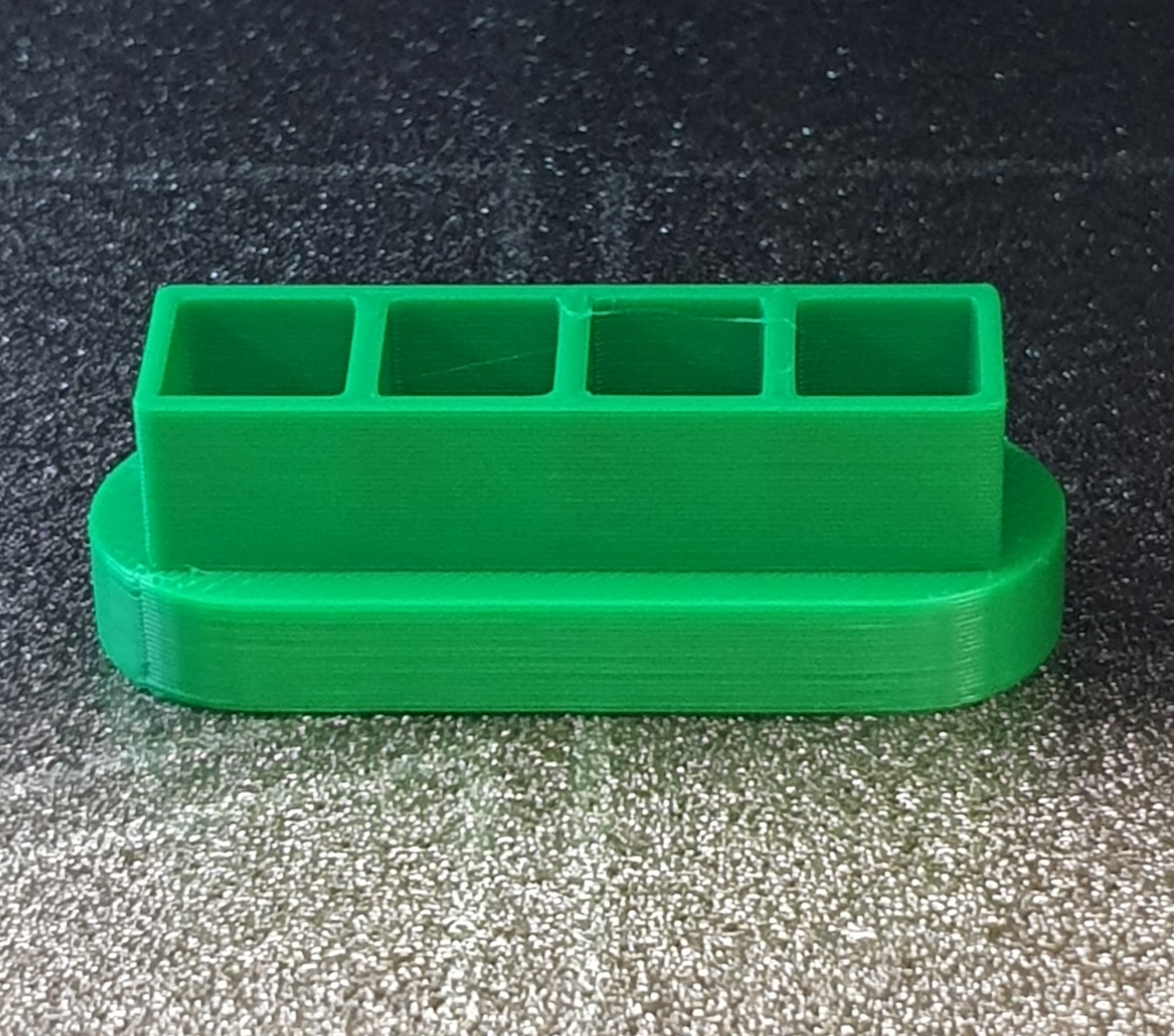 Final home made sample for all pillars Contact me for the details |
See it printing
 |
This ZIP contains the Blender scripts to generate the Socket and Sleeves. They can be used or modified and the objects exported to ST. The STL can be printed on the Bambu P1S.or compatible 3D printer. The ZIP contains an STL ready for printing without needing Blender. 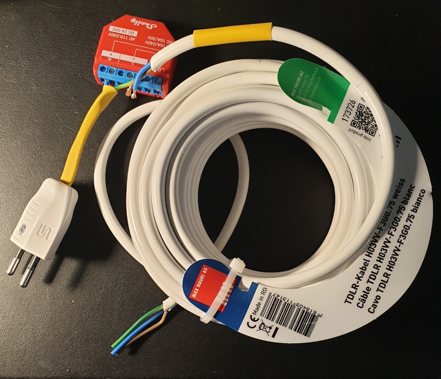 10 m of 0.75 cable being connected up Live 230v connections are exposed - proper protection must be ensured. 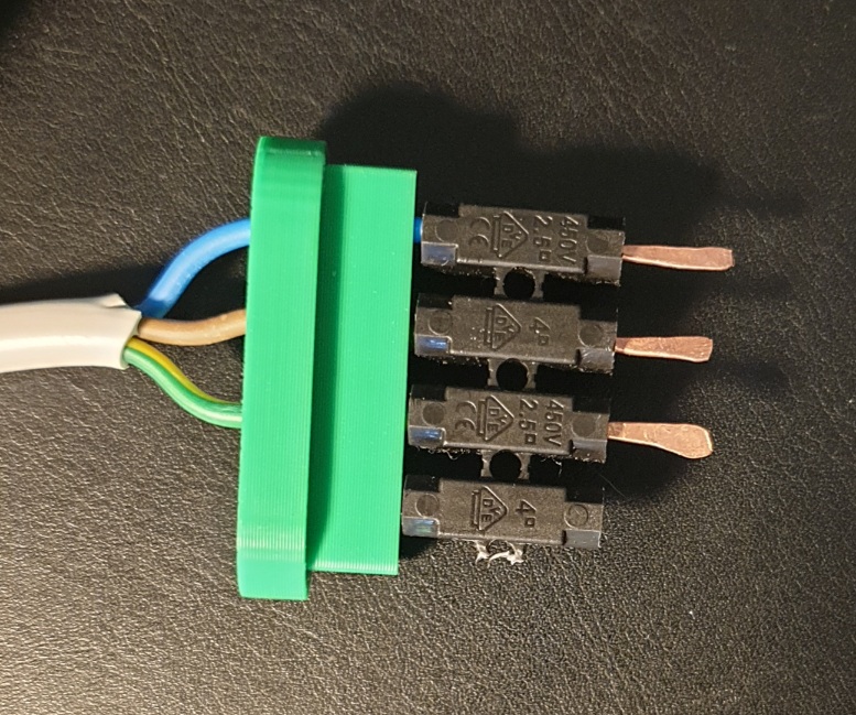 With wires installed for European use and temporary home made terminals
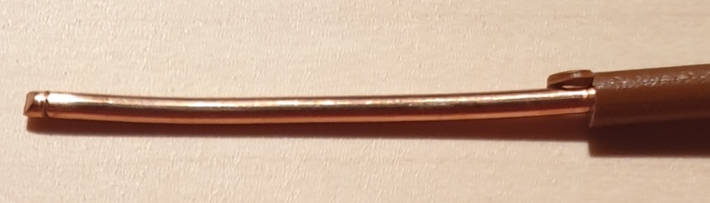
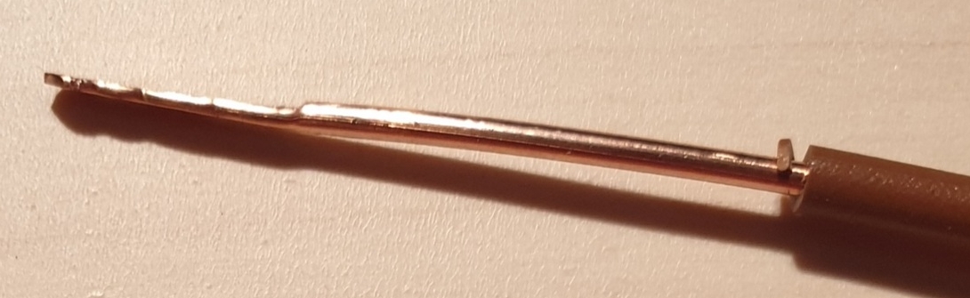
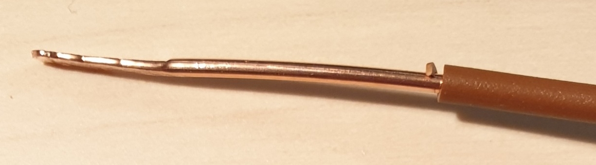
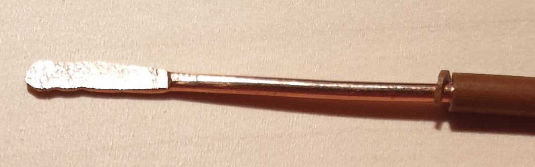
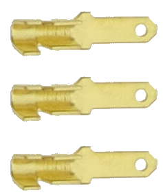 Eventually proper 2.8 mm terminals are to be installed 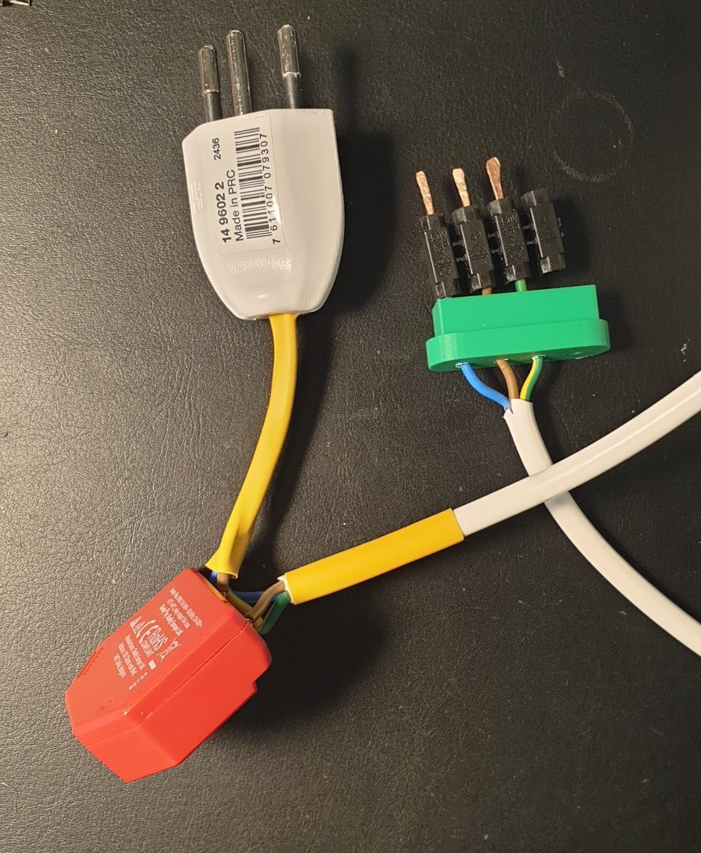 In the absence of real terminals makeshift ones were used A length of denuded 1.5 mm copper house wire was hammered on the end till it made a flat spade and 3 portions made then joined with a connector strip to the wire ends matching pillar spacing almost exactly 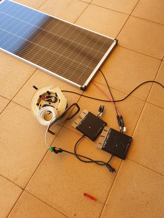 Using a cheapy solar panel as power source each inverter could be tested Making of the temporary home made spades
| |||||||||||
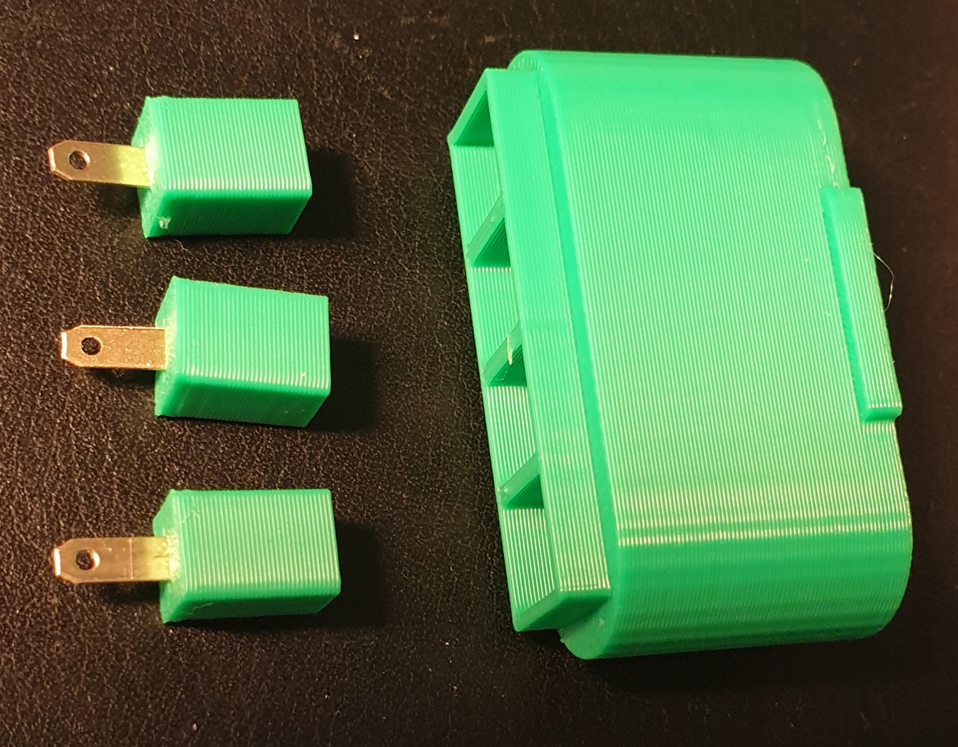 The final components ready to install sockets and locating sleeves 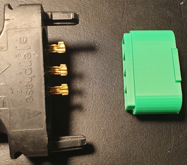 checking the socket and pin fits 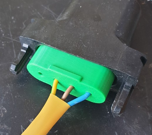 Socket finally installed and operational Notes: 1. this is not waterproof and cannot be left outside 2. power source must not be connected when handling 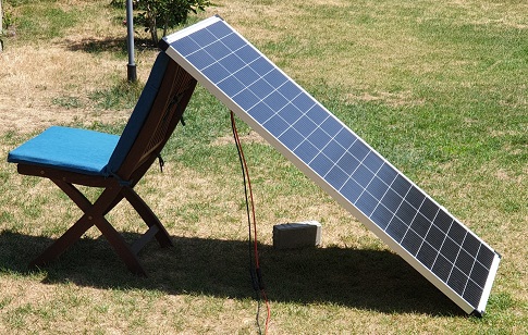 Live testing the inverter with a cheap 200 W panel [Laid flat 1.1 kWhs, fully oriented 1.5 kWhs in July] How will the test be setup and verified The Shelly can be used to turn on/off power to the inverter and once the inverter is operating, measure production and if the inverter is faulty it will be apparent. The inverter can produce a maximum of 1.2 A and the cable can carry > 5 A This setup allows many inverters to be swapped in and out or left in production. Expected Inverter lights. 1. Connecting sunlit solar panel MC4 DC power source to inverter. The LED will flash Green 6 times. Meaning the micro inverter is healthy. 2. Turn Shelly on - The LED will begin Flashing Amber/Orange slowly (once every few seconds). meaning the inverter successfully detects the AC grid connection. European regulations require a mandatory 5-minute countdown timer before the inverter is allowed to interact with the grid. During these 5 minutes, it is monitoring the voltage (230V) and frequency (50Hz) to ensure stability. 3. Successful Operation State after the 5-minute monitoring window closes The LED will transition to Flashing Green slowly. Meaning the inverter is fully operational and trying to produce power/sync with the grid loop. The Shelly should show current, dependent on the amount of sunlight on the panel. Errors 4. Flashing Red means the inverter does not detect the AC grid. 5. Solid Red: A critical hardware fault or a Ground Fault (GFI). Shelly must be turned off. 6. At night or no MC4 connected the light will be off, even if mains available. Bonus 7. With a known good inverter it can test if a panel is working no lights will appear when the panel is sunlit. |
|||||||||||
|
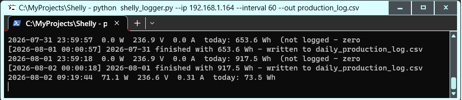
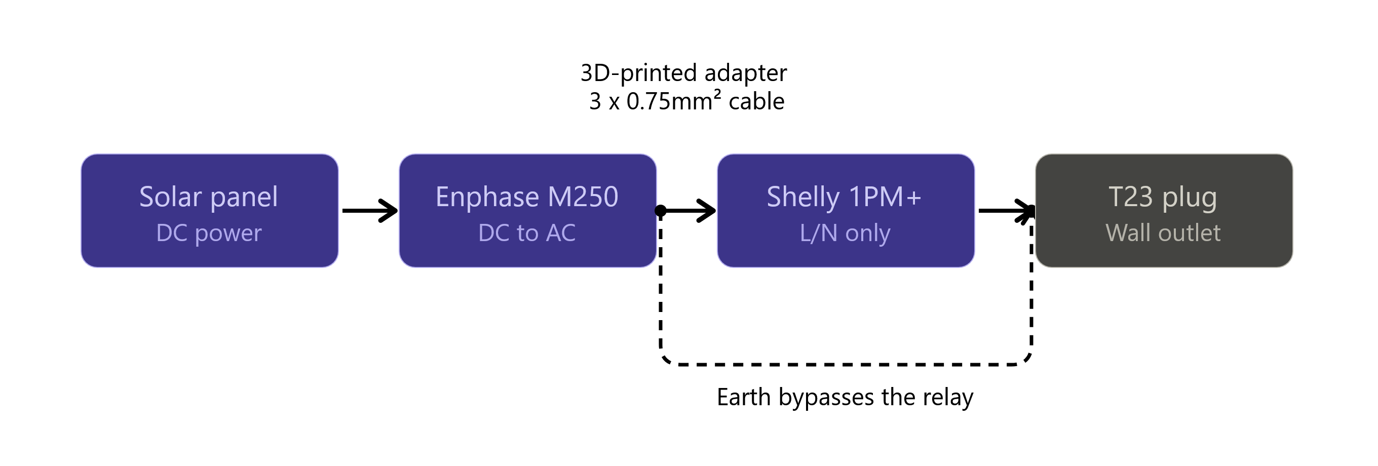
Setup the Shelly 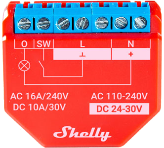 Power to L + N Inverter to O + N Plug in the Shelly and switch phone to it's WiFi AP in the browser enter 192.168.33.1 This brings up the WiFi configuration page Enter your router SSID [selectable] and password It should reboot connecting to your router AP on your phone enter it's network IP address and then it's ready for use. If the inverter is working with the Shelly switched on you should see how much is being generated 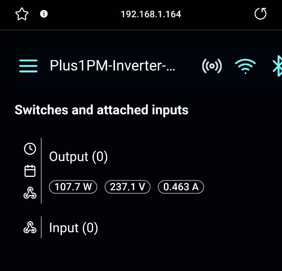 Caveats and notes 1. The testing circuit is confirmed for European inverters of all sorts that use 2 or 3 active pins [of the 4 pins] in the plug that is compatible with any Engage cable irrespective of single or 3 phase systems. 2. The Shelly was chosen as a cheap universal plug independent cloud free solution Other devices, such as myStrom, TP-Link Tapo P110, Sonoff POWR316D [and others] are also candidates but probably overkill for this simple task. 3. Should the system be left connected it is not weather proof consider using MC4 extension cables to keep the inverter and its connections in a dry place. 4. Should you want a consumption log use a locally running logger such as Download Shelly-logger.zip, unzip it to a folder, right click and unblock. To run it on a PC with Python installed open a cmd prompt on the folder where the file is stored and run the command, adjusting appropriately python shelly_logger.py --ip 192.168.1.50 --interval 60 --out production_log.csv if you encounter errors make sure all imports are installed via the pip command as shown in the program. 5. Should you want to add it to a production system, it is also possible if the gateway can see it, run a scan to locate it. The cabling of the plug wires given above is confirmed after examining an inverter internals. 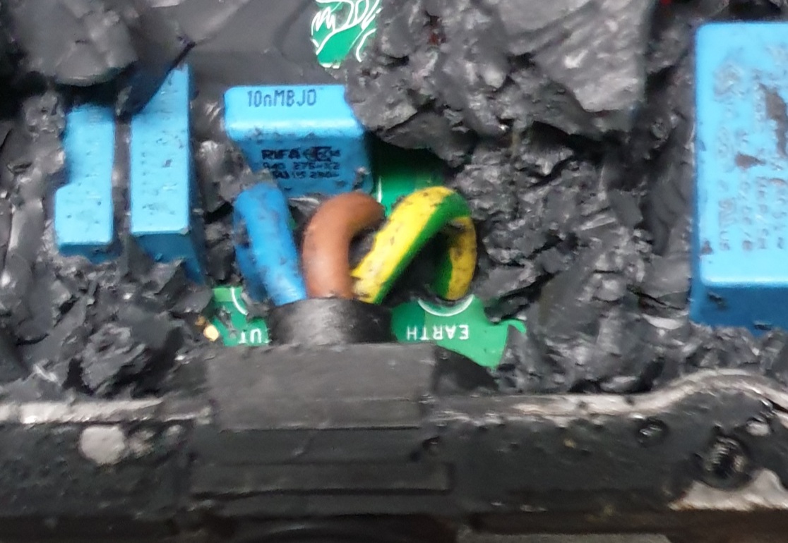 The pillar colours on the plug are in order: Dummy, Ground [green/yellow], Live [brown] and Neutral [blue]. Verified from an actual inverter 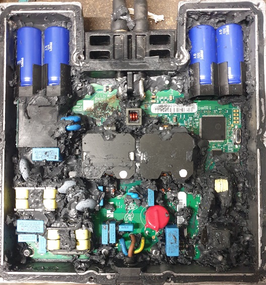 Enphase M250 inverter partial Teardown |