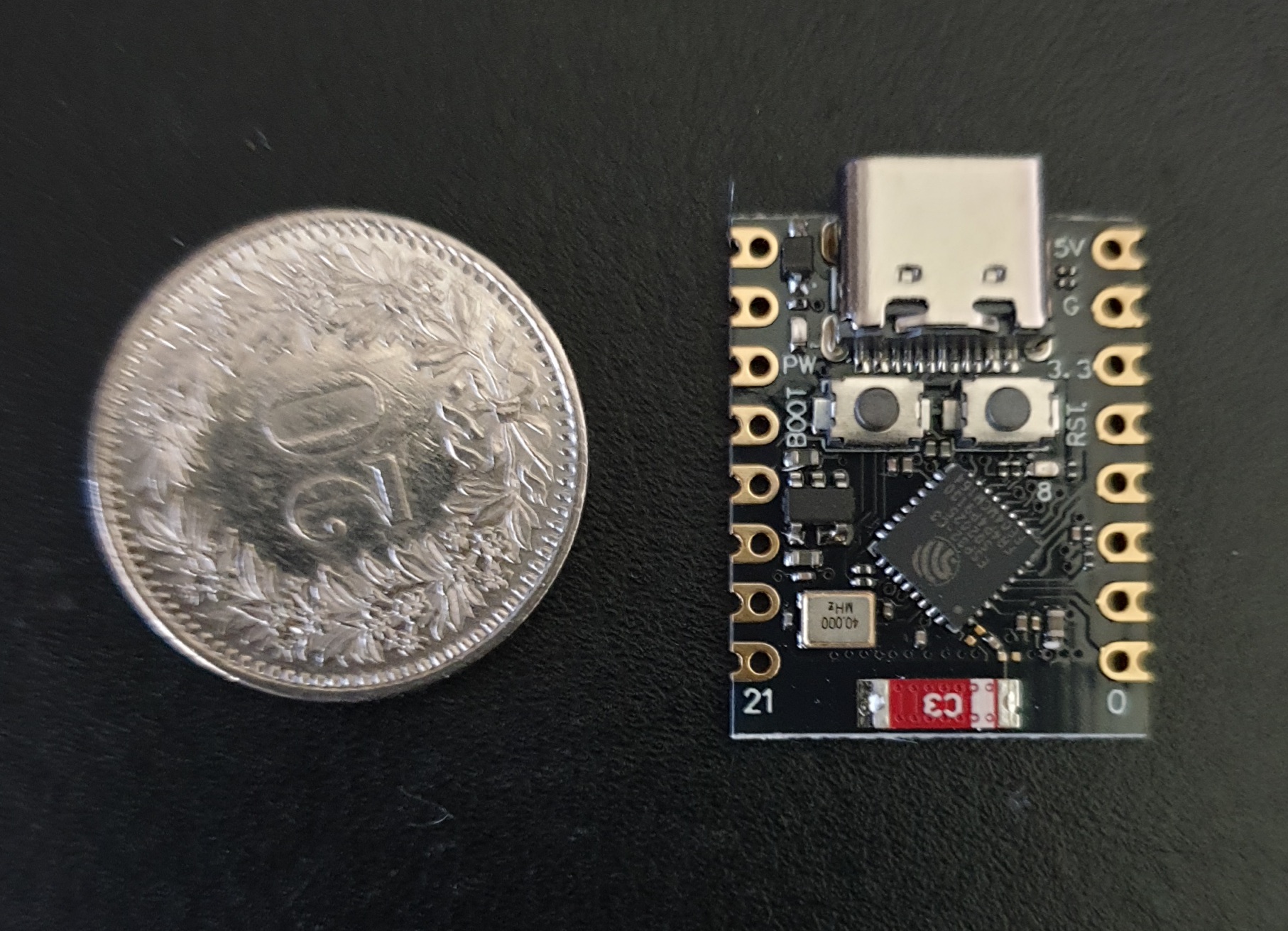
ESP32 C3 Super mini
How to start using this device
 |
Setup preparation
Open Device Manager
Open Device Manager
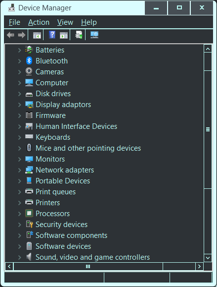
Plug in the device to a USB port
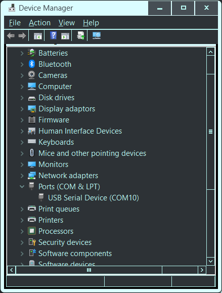
You will see a Port and COM number.
This may disappear again.
To establish a permanent connection for installing firmware
Press the Boot button, then the Restart button
Release the Restart button and then the Boot button
You should now have the device connected permanently in Device Manager
and ready to receive firmware or talk on the port shown.
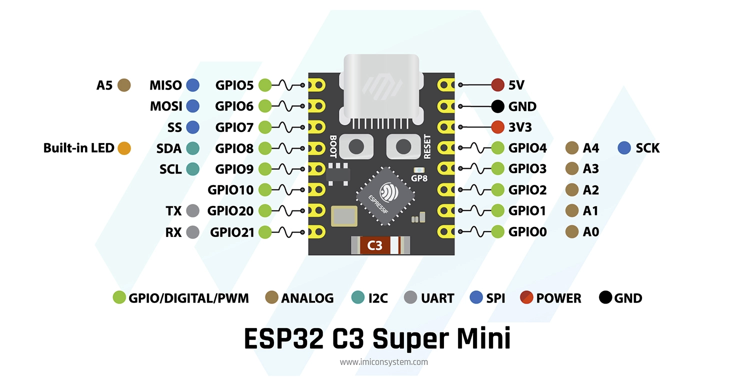 |
ESP32 C3 Super mini multi purpose monitor/controller pin outs
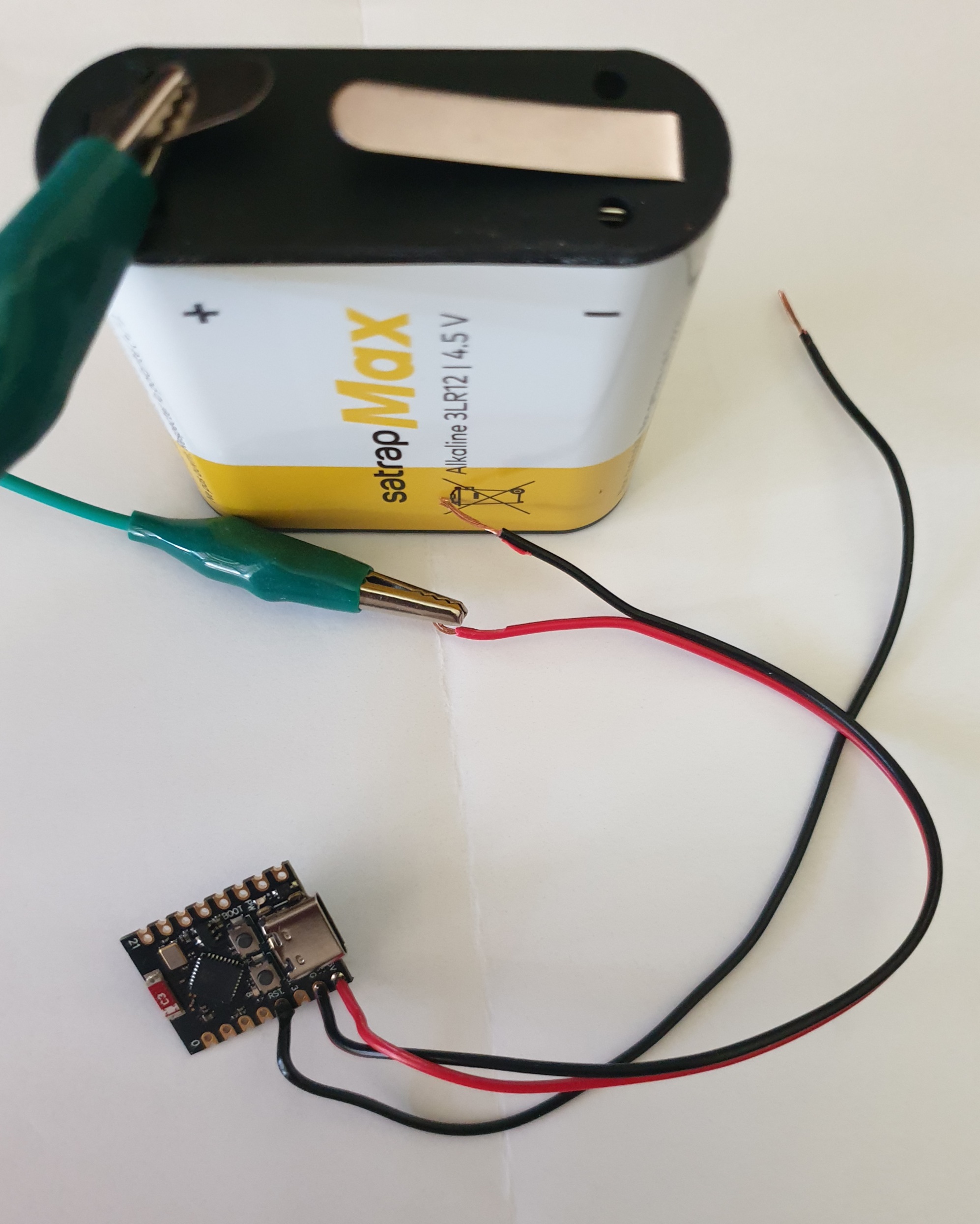
Should run from a 4.5V battery till about 3.5V
Deep Sleep mode 50 micro amps [without power led]
< 8 ma to wake and check for < 100ms
~ 85 ma for < 1 second to report
Battery life span several years
To remove the red Led unsolder or break with a tiny screw driver
Replace with Blue light briefly ON at start up in the code
Don't use GPIO2 or GPIO9 with deep sleep
these pins have special state at start up.
Characteristics
Should run from a 4.5V battery till about 3.5V
Deep Sleep mode 50 micro amps [without power led]
< 8 ma to wake and check for < 100ms
~ 85 ma for < 1 second to report
Battery life span several years
To remove the red Led unsolder or break with a tiny screw driver
Replace with Blue light briefly ON at start up in the code
Don't use GPIO2 or GPIO9 with deep sleep
these pins have special state at start up.
Installation
How to get this running simply and quickly
Connect the board as a serial port of your PC via a regular USB cable. as described
In Visual Studio Code, install PlatformIO IDE
It will need these parameters in its platformio.ini
Adjust the COM to the one for the serial port in Device Manager
"Do I need Visual Studio Code?"
No. For beginners or casual users, the free Arduino IDE is simpler and does everything you need to get started with ESP32 programming.
Adjust the COM to the one for the serial port in Device Manager
"Do I need Visual Studio Code?"
No. For beginners or casual users, the free Arduino IDE is simpler and does everything you need to get started with ESP32 programming.
|
; PlatformIO Project Configuration File
; ; Build options: build flags, source filter ; Upload options: custom upload port, speed and extra flags ; Library options: dependencies, extra library storages ; Advanced options: extra scripting ; ; Please visit documentation for the other options and examples ; https://docs.platformio.org/page/projectconf.html [env:esp32c3mini] platform = espressif32 ;board = esp32-c3-devkitc-02 board = esp32-c3-devkitm-1 framework = arduino monitor_speed = 115200 upload_port = COM10 build_flags = -DARDUINO_USB_MODE=1 -DARDUINO_USB_CDC_ON_BOOT=0 |
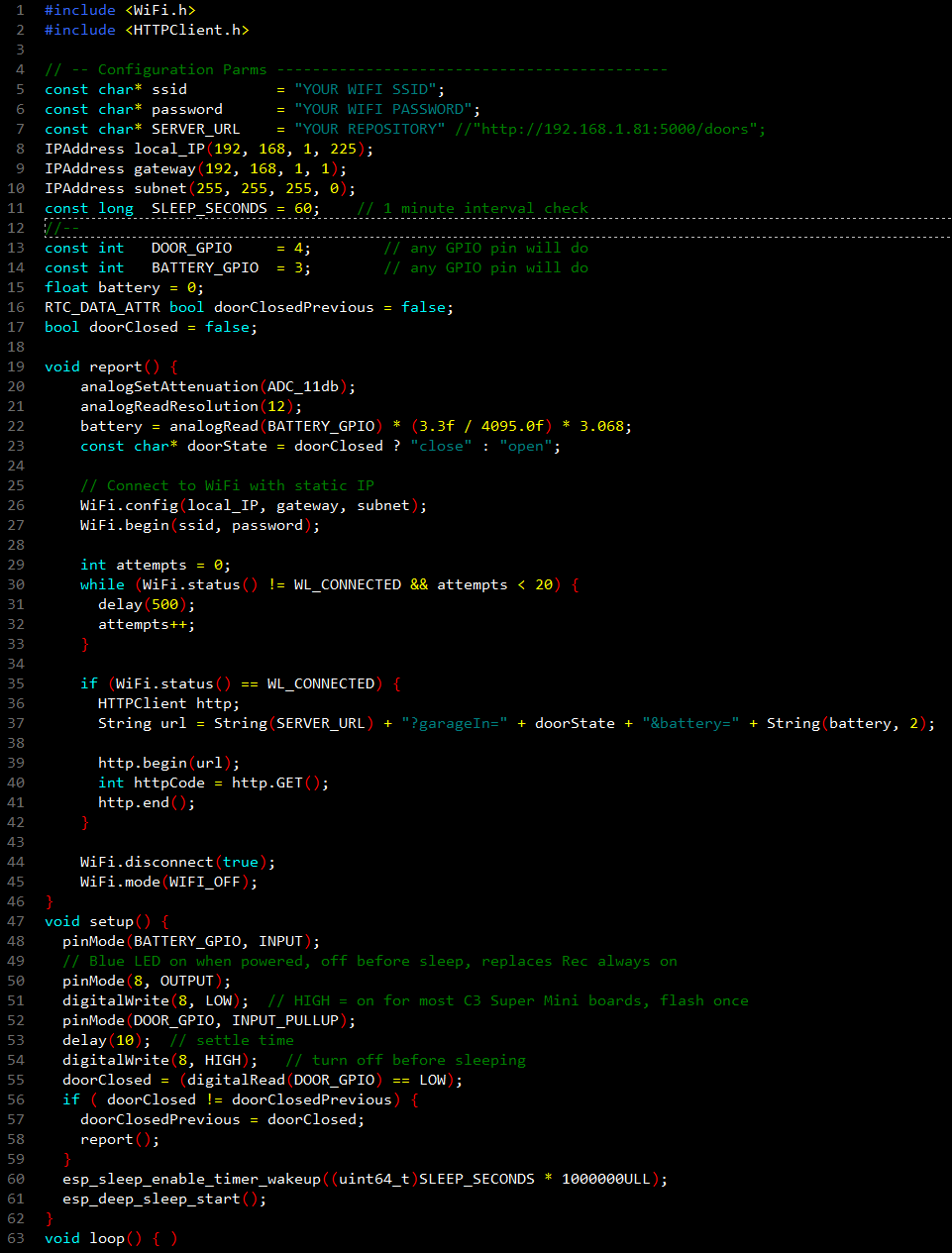
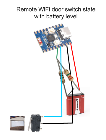
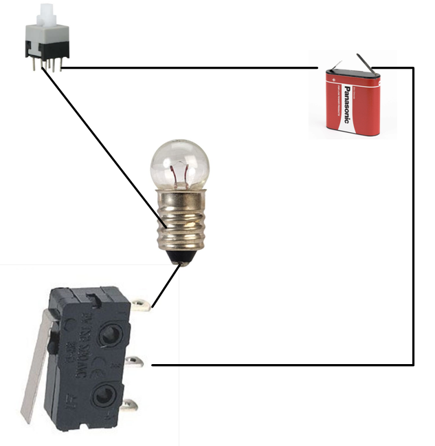
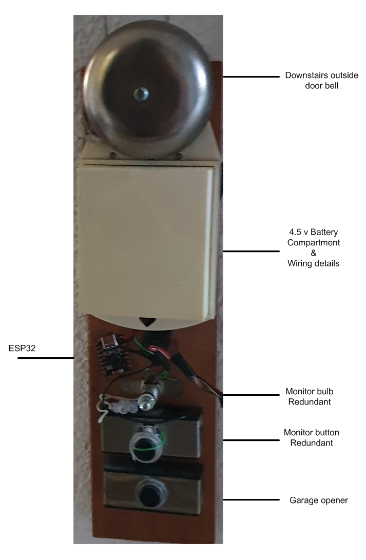
Door Switch monitor application
- which reads door switch on GPIO 4
- which reads battery level on GPIO 3
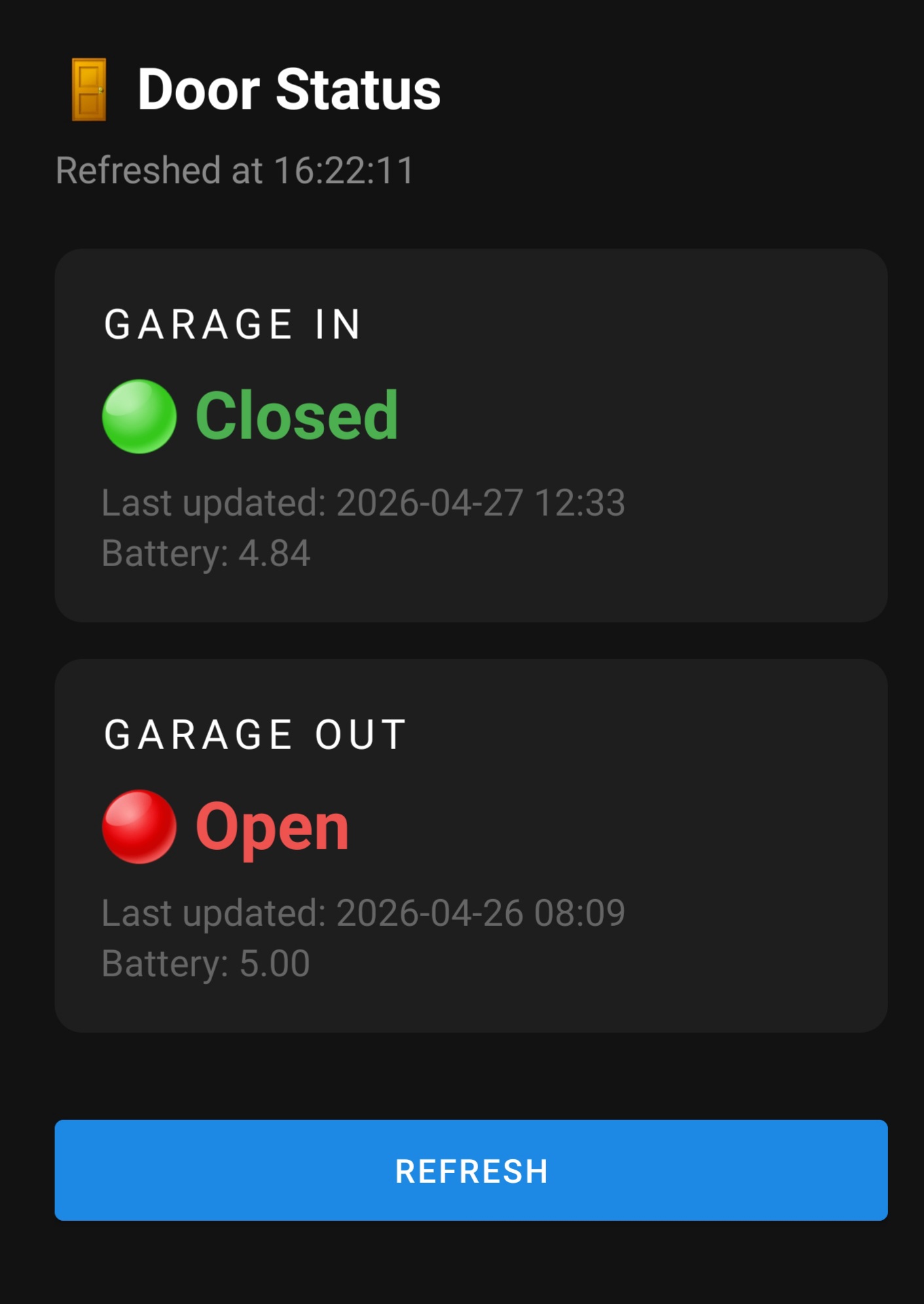
- reports any change back to repository over WiFi, like
- http://<ip>/doors?garageIn=close&battery=4.61
- takes < 1 second to record a change
- takes < 100 ms per poll
Save it as main.cpp for your project
Enter the following details
your SSID
password
reporting address [such as a Home Assistant]
unique IP address details
choose default poll time, default 60 seconds
Build and upload
The light will flash and it will sleep
Each polls senses if switch is open or closed
usually from a simple door switch
any change is recorded over wifi
It will flash and then sleep again
The details can be retrieved from where it reported to