ESP32 How to start using this device


Setup


Basic architecture


schema


sd card

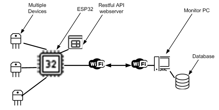
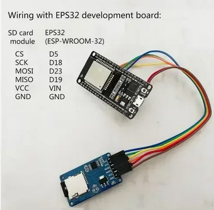
Purely Optional

SPI (for SD card)

Function Default GPIO
MISO 19
MOSI 23
SCK 18
CS 5

esp32

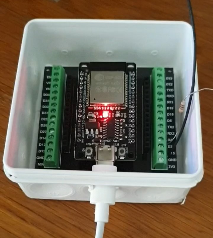
ESP32 multi purpose monitor/controller

See pin outs below


✅ Parts List (click image to locate the correct model)

  • 1x ESP32 (3.3V logic and development board) ($6.56)

  • External SD card module (purely optional $4.43 for 5)

  • PC or 5v independent power supply and cable


Installation

How to get this running simply and quickly

Connect the board as a serial port of your PC via a regular USB cable

Unpack and install the serial driver for this board, using the CH3400 chip serial driver   [ Source]


In Visual Studio Code, install PlatformIO IDE

It will need these parameters in its platformio.ini
Adjust the com to the one for the serial port in Device Manager

"Do I need Visual Studio Code?"
No. For beginners or casual users, the free Arduino IDE is simpler and does everything you need to get started with ESP32 programming.


; PlatformIO Project Configuration File
;
;   Build options: build flags, source filter
;   Upload options: custom upload port, speed and extra flags
;   Library options: dependencies, extra library storages
;   Advanced options: extra scripting
;
; Please visit documentation for the other options and examples
; https://docs.platformio.org/page/projectconf.html

[env:fm-devkit]
platform = espressif32
board = fm-devkit
framework = arduino
monitor_speed = 115200
upload_port = COM8


ESP32D Pin mapping
(click table for installable program guide code)

Left side pins (from top to bottom)

| Label | GPIO Number   | Notes             
| ----- | ------------- | -------------------
| EN    | Reset pin     | Not GPIO          
| VP    | GPIO36        | Input-only (ADC)
| VN    | GPIO39        | Input-only (ADC)
| D34   | GPIO34        | Input-only (ADC)
| D35   | GPIO35        | Input-only (ADC)
| D32   | GPIO32        | ADC, can be input
| D33   | GPIO33        | ADC, can be input
| D25   | GPIO25        | DAC, can be output
| D26   | GPIO26        | DAC, can be output
| D27   | GPIO27        | ADC, can be input
| D14   | GPIO14        | PWM, SPI, I2C 
| D12   | GPIO12        | PWM, SPI, I2C
| D13   | GPIO13        | PWM, SPI, I2C
| GND   | Ground        | Ground pin  
| VIN   | Input voltage | Power in 5V in/out
|       |               | out =< 500 ma  

Right side pins (from top to bottom)

| Label | GPIO Number   | Notes       
| ----- | ------------- | ---------------
| D23   | GPIO23        | PWM, SPI      
| D22   | GPIO22        | PWM, SPI, I2C 
| TXD   | GPIO1         | UART0 TX     
| RXD   | GPIO3         | UART0 RX   
| D21   | GPIO21        | PWM, I2C  
| D19   | GPIO19        | PWM, SPI          
| D18   | GPIO18        | PWM, SPI           
| D5    | GPIO5         | PWM, SPI              
| TX2   | GPIO17        | UART2 TX            
| RX2   | GPIO16        | UART2 RX             
| D4    | GPIO4         | PWM, SPI               
| D2    | GPIO2         | Built-in LED, some
| D15   | GPIO15        | PWM, SPI             
| GND   | Ground        | Ground pin         
| 3V3   | 3.3V Power    | Power pin max 300ma  

Notes:

    Pins VP (GPIO36), VN (GPIO39), D34 (GPIO34), D35 (GPIO35), D32, and D33 are ADC-capable input-only pins.
    They cannot be used as digital outputs.

    Pins like D25 and D26 have DAC (digital-to-analog converter) capability.

    Pins labelled TXD/RXD correspond to the UART serial pins.

    Pins like D2 (GPIO2) often have an onboard LED on some ESP32 boards.

    EN is not a GPIO pin; it's the enable (reset) pin.

Summary usage:

    Use the GPIO numbers in code, e.g., digitalRead(34) or digitalWrite(2, HIGH).

    Do not to use input-only ADC pins as outputs.

    You can use most of the pins for PWM, SPI, I2C, UART, or digital IO as shown.
   
    max GPIO output 12 ma per pin, Use resistors when driving LEDs (eg. 220-330 Ohms). max total 120 ma
   
    Input consumption ~50 ľA typical
   
    No pin tolerates < 0 V or > 3.6 V


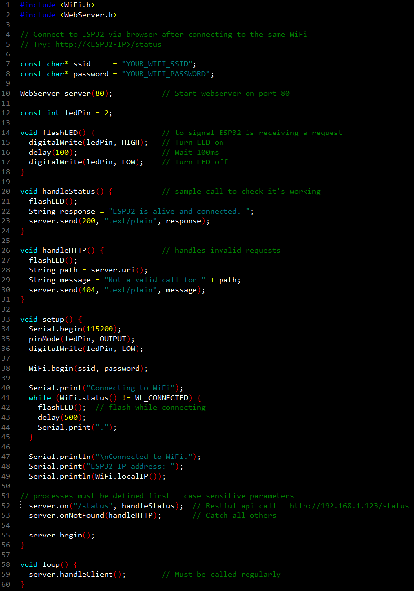
Sample program [click on it to access raw code]
Save it as main.cpp for your project
Enter your ssid and password
Build and upload
The light will flash till wifi is connected
In the monitor [ctrl+Alt+s] your IP is shown
In the browser enter HTTP://<IP>/status
                                                                        

sample

Video thumbnail

Play icon