ESP32 project to monitor electrical activity at home


Design a compact sensor for multiple cables in a wiring closet
that can detect in use [and roughly by how much]

Make sure to follow the Setup first


ss49E


8 x SS49E 3.3v Hall effect


core

Ferrite core

ADS1115

2 x Quad OP amp

I²C (for ADS1115)

FunctionDefault GPIO
SDA21
SCL22

Each Quad amp can read 4 hall sensors


sd card

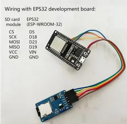
Purely optional

SPI (for SD card)

FunctionDefault GPIO
MISO19
MOSI23
SCK18
CS5


esp32

  ESP32 monitor/controller

Support 2 Quad amps
with 4 devices each
Total 8 circuits per EPS32

See pin outs below


wiring

Sample wiring for one sensor via op amp

Micro CT

First Prototype device

comparison

Comparison with a Mini CT

Test circuit

Sample test circuit with mini, micro and normal CTs


How was this tested and calibrated

The brown mains live wire was powered by a Shelly 1PM switch which measures the current passing.
The factor was adjusted for the micro CT to display the same current
Increasing the current causes the micro CT to show a similar increase linearly
Values achievable are accurate to within a few 10s of ma.
 

How was the prototype installed

Needing to power off the main board we needed lighting to work on it
and used an old APC 350W UPS with a car battery
connected to a LED strip light

Circuit board lighting


Considered a homemade spacer but it wasn't necessary

spacer


Before and after installation

original board

Original board (3 Phases)
A= Ground floor heating
B = 1st floor heating
Installed prototype


Converted board with
prototype sensors


Values returned by Restful API call

WebCmd http://192.168.1.227/CT?Status=

GuyTec - Micro CT Status Report: at 2025-10-24T03:15:25.088 (DST:1)

Channel: 0 7.455 at: 03:15:24 factor: 62.4500 active: true  Power: 1.6597 Use: Daikin
Channel: 1 1.135 at: 03:15:24 factor: 58.8300 active: true  Power: 1.6491 Use: Office
Channel: 2 0.000 at: 01:04:22 factor: 62.0000 active: true  Power: 1.6491 Use: GHeat-P3
Channel: 3 0.000 at: 02:58:55 factor: 60.2000 active: true  Power: 1.6648 Use: 1Heat-P3
Channel: 4 0.000 at: 21:10:55 factor: 58.0800 active: true  Power: 1.6653 Use: GHeat-P1
Channel: 5 0.000 at: 00:41:48 factor: 71.3530 active: true  Power: 1.6960 Use: 1Heat-P1
Channel: 6 3.208 at: 03:14:34 factor: 65.0000 active: true  Power: 1.6435 Use: GHeat-P2
Channel: 7 0.000 at: 02:58:57 factor: 70.0000 active: true  Power: 1.6317 Use: 1Heat-P2
maxDevices: 8  Amplifiers: 2
Log (version 8):
2025-10-02T19:40:04.375 (DST:1) - Power On


Sample monitoring with current values and live solar

mini view


Mini view
PowerMonitor full view

Full view

End of day results


Date        Unit CH       Circuit  Time     Solar   Grid    Total (kWh)
2025-10-24  227  0         Aircon  23:43:00  2.4208 16.3158 18.7366
2025-10-24  227  1         Office  23:46:30  1.1178  2.5277  3.6455
2025-10-24  227  2          GHeat  01:04:30  0.0037  0.0202  0.0239
2025-10-24  227  3          1Heat  08:35:30  0.8916  5.8434  6.7350
2025-10-24  227  4          GHeat  00:22:00  0.0046  0.0079  0.0125
2025-10-24  227  5          1Heat  00:18:30  0.0052  0.0046  0.0098
2025-10-24  227  6          GHeat  07:43:30  0.8270  4.4727  5.2997
2025-10-24  227  7          1Heat  04:32:30  0.9001  6.3126  7.2127


What was discovered so far with this prototype

Readings quite accurate and stable

results to within < 10 W [GHeat P2 745-753 W, source 750 W device]
not impacted by proximity to other wires or current draws, so far

Aircon when off uses ~ 65 W [quite unexpected]

Absolutely delighted with the outcome,
however the sensors were too delicate and fiddly to install.
A new design for the sensor, with a short sleeve shirt, is being developed
This will make it easier to calibrate and install consistently

short sleeve shirt

Initial design for a 3D print
Cardboard cut-out from a 3 bar Kägi chocolate packet

✅ Parts List

For monitoring up to 8 current circuits using:

  • 8x SS49E Hall sensors (10 - $2.73)

  • 2x ADS1115 ADC boards ($2.82)

  • 1x ESP32 (3.3V logic) ($6.46 for 2, 1 spare)

  • Ferrite core (10 x 3.5mm $4.38)

  • External SD card module (purely optional $4.43 for 5)

Total cost for necessary parts $23.80, including postage,
only a few lengths of cat 5e cable need extra ($3 per circuit measured)

  • use 3.3V power throughout

  • ADS1115 gain set to 1x for best sensitivity

✅ System Overview

  • SS49E sensors produce analog voltages centered around 1.65V (for 3.3V supply) and shift up/down with current.

  • ADS1115 reads 4 analog voltages per chip with one x gain.

  • ESP32 communicates with the 2 ADS1115 via I²C and handles signal processing.


Wiring and Connections

SS49E Sensors (x8)

Pin Function Connection
VCC +3.3V 3.3V rail from ESP32
GND Ground GND rail from ESP32
OUT Analog signal A0–A3 on ADS1115 (x2)

Cable tie to wire to be measured at 90 degrees inside a ferrite

Connect using a twisted pair for OUT and GND.
Connect using a twisted pair for VCC and all non-connected wires grounded at source end.


ADS1115 (x2 units)

  • Address A0 pin LOW (0x48) for one and HIGH (0x49) for the other, to use both on same I²C bus.

ADS1115 Pin Function Connect to ESP32
VDD +3.3V 3.3V
GND Ground GND
SDA I²C Data GPIO 21
SCL I²C Clock GPIO 22
A0 Addr select GND (0x48) / VCC (0x49)
AIN0–AIN3 Analog inputs Connect to SS49E OUTs

ADS1115 Gain Setting

  • Use Gain = 1 (±0.256V input range)

  • This gives maximum resolution for small shifts (16-bit over 0.512V span)

  • Code - ads.setGain(GAIN_ONE);

ESP32 I²C Pinout (Default)

Function ESP32 GPIO
SDA GPIO 21
SCL GPIO 22

Sample ESP32 Code Snippet (Pseudocode)

ads.setGain(GAIN_ONE); // ±0.256V
int16_t value = ads.readADC_SingleEnded(0);